System integration in scientific instruments: How subsystems work together
Scientific instrument system integration brings fluidics, mechanics, sensing, electronics and software together into one working system. This article explains how subsystem interfaces, interactions and testing influence scientific instrument development and why integration should be considered from the start.
A scientific instrument rarely depends on a single technology.
Depending on the application, it may combine fluidics, sensing, optics, mechanics, electronics, temperature or pressure control, software and data acquisition. Each subsystem can work correctly on its own and the complete instrument can still fail to behave as expected.
.png)
This is the challenge of system integration.
Integration is not simply about connecting finished components. It is about understanding how those components interact, what they require from one another, and whether the complete system still supports the scientific process it was designed for.
1. Define how the system needs to work together
Before integrating components, it helps to define the functions the instrument needs to perform.
A system might need to introduce a sample, establish controlled conditions, move or position it, measure a response, adjust an operating parameter and record the result.
Those functions may belong to different engineering disciplines, but they are connected by the experiment.
For example, an optical detector may require the sample to remain in a specific position. A microfluidic process may depend on a defined pressure or flow condition. A temperature-sensitive assay may require the heater, sensor and control software to respond together.
This creates dependencies between subsystems.
A useful integration plan therefore asks:
- What does each subsystem need from the others?
- What information or material crosses between them?
- Which interactions could influence the scientific result?
- Which operations need to happen in a particular sequence?
- What does the user need to connect, adjust or monitor?
Thinking about these questions early helps prevent individual components from being developed around assumptions that become incompatible later.
2. Pay attention to the interfaces
Many integration problems occur at the boundaries between subsystems.
These interfaces may be mechanical, fluidic, electrical or digital.
In microfluidics, a clear example is the connection between a chip and the external fluid-delivery system. The microchannels may be only tens or hundreds of microns wide, but samples and reagents still need to move between the chip and macroscale components such as reservoirs, tubing and pumps
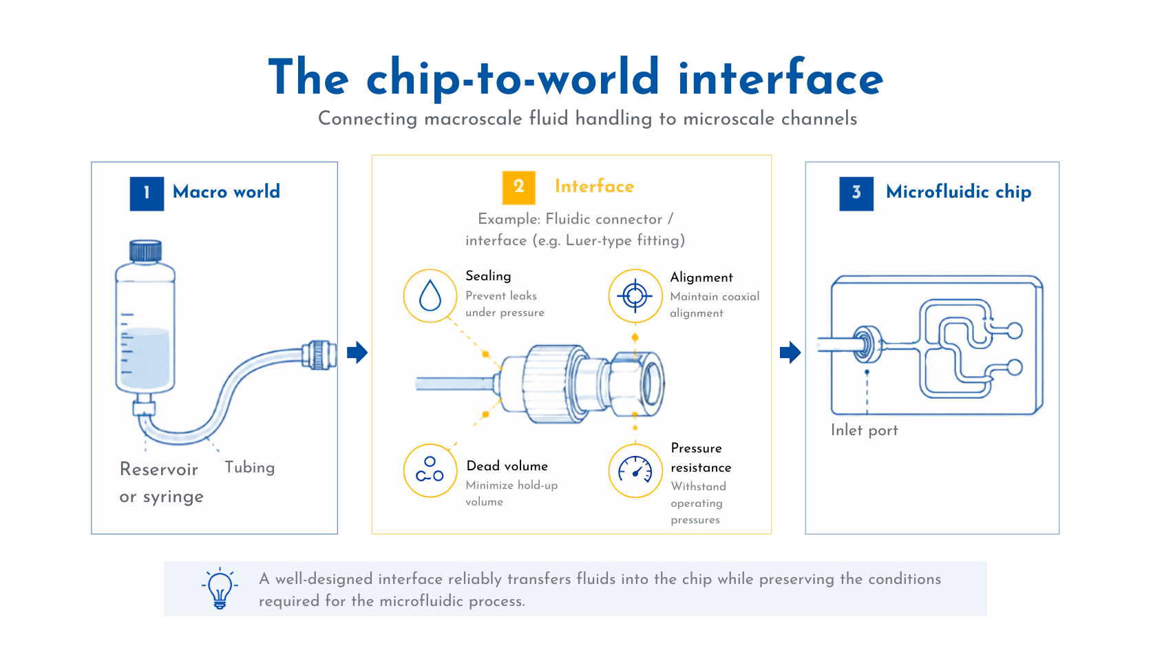
This has long been recognised as the chip-to-world, or macro-to-micro, interface problem in microfluidics. [1]
Several solutions are possible. Tubing may be inserted directly into a device, or connected using fittings, manifolds, gaskets and standardised connections such as Luer-type connectors. Reusable multichannel interfaces have also been developed for chips made from materials including glass, polymers and PDMS. [2]
There is no universal best interface.
The appropriate solution depends on factors such as operating pressure, fluid compatibility, dead volume, number of connections, chip material and how frequently the user needs to connect or replace the device.
The same principle applies throughout an instrument.
A mechanical interface needs to maintain alignment. An electrical interface needs compatible signals and power. Software needs a reliable way to communicate with sensors and actuators.
An interface is therefore not simply the space between two completed designs. It is part of the system design itself.
3. Expect subsystem behaviour to change after integration
A component specification describes how a component performs under particular conditions. Those conditions may change once it becomes part of an instrument.
A pump connected to tubing, reservoirs and a microfluidic chip experiences a different fluidic load from the pump alone. Adding tubing can change resistance and compliance. A sensor placed into the flow path can alter the system it is measuring.
Similar effects appear outside fluidics.
Mechanical vibration can interfere with sensitive measurements. Electronics introduce heat. A larger enclosure may change thermal behaviour. Software and communication delays can affect the timing between sensing and actuation.
This is why system integration needs more than checking whether each component operates.
Our embedded pressure-control platform provides a practical example.
Pressure regulation was not developed as a standalone function and then simply placed inside an instrument. The architecture was designed around integration, using distributed control Nodes coordinated by a Master controller. Mechanical, pneumatic, electrical and communication interfaces all had to work as parts of the same system.
Development therefore included stability testing, response-time characterisation and multi-channel synchronisation rather than only verifying that an individual regulator could produce pressure.
The relevant question was how the pressure-control subsystem behaved once connected to the application around it.
4. Integrate and test the complete workflow
System integration should be tested progressively.
Individual components can first be characterised independently. Related components can then be combined into functional subsystems before the complete instrument is assembled and tested under realistic operating conditions.
This makes unexpected interactions easier to identify.
Testing should also follow the workflow rather than stopping at hardware performance.
- Can the user introduce the sample reliably?
- Do fluidic connections seal consistently?
- Does the sensor receive the sample under the expected conditions?
- Do control systems respond at the right time?
- Can the workflow move from one stage to the next without unnecessary setup or intervention?
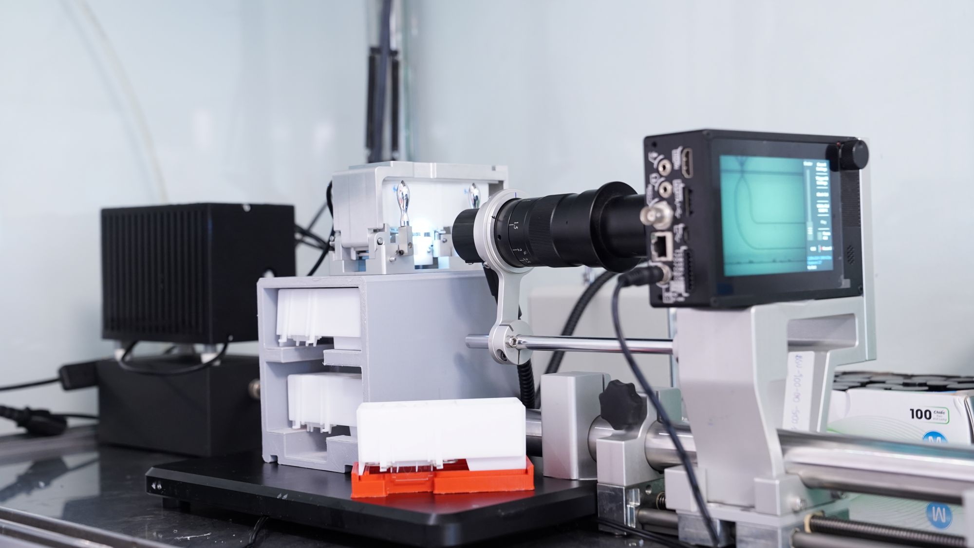
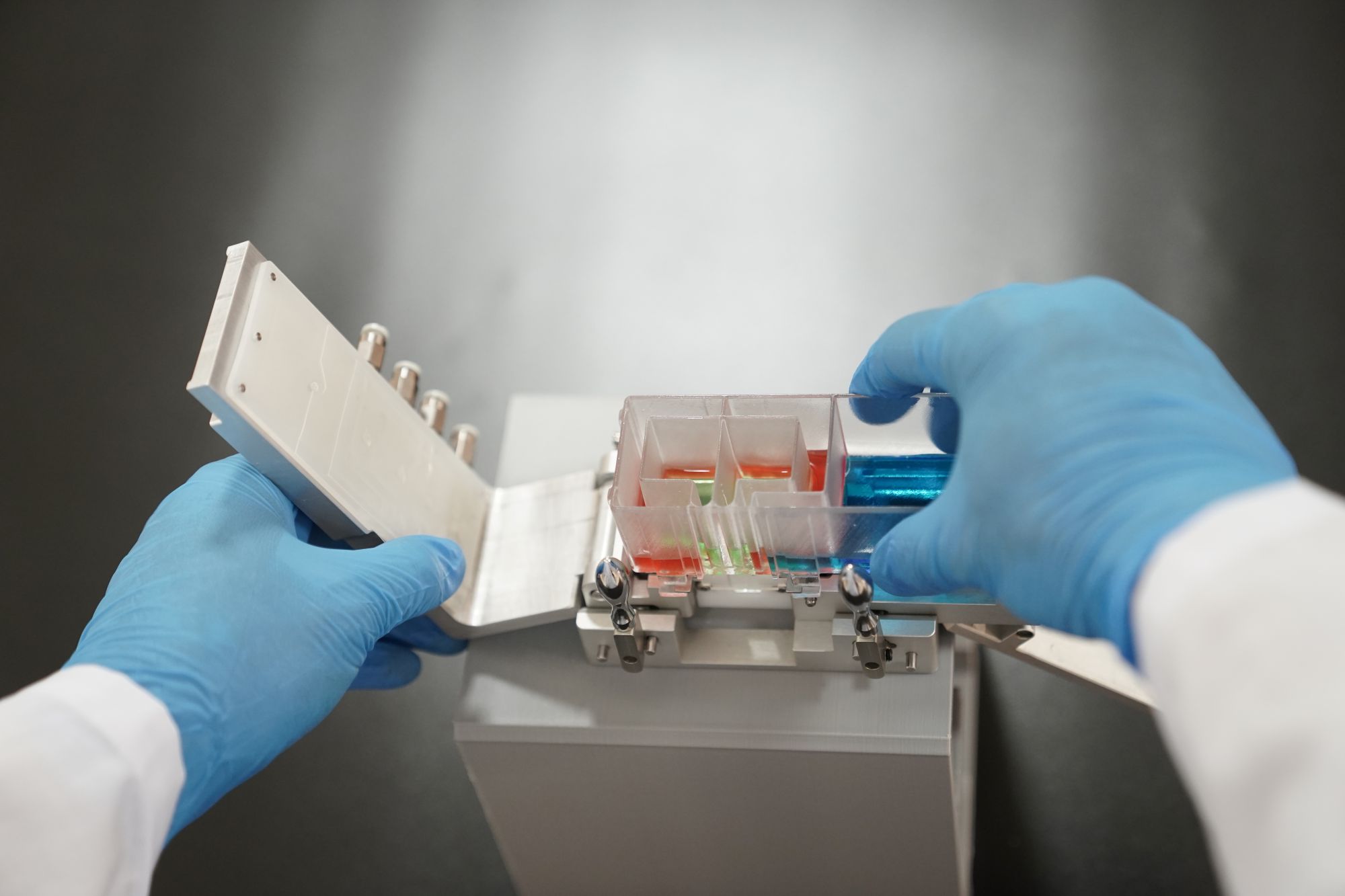
Our modular tubeless microfluidic platform developed from this type of system-level problem. The original experimental setup combined tubing, reservoirs, chip holders and alignment components. The individual technologies worked, but the interfaces between them made frequent experimental changes slow and cumbersome.
The redesigned platform brought chip handling, sealing and fluid delivery into a cartridge-based system, reducing the number of separate connections and simplifying how researchers interacted with the setup.
In both this project and the pressure-control platform, the core lesson was similar.
Good system integration is not about fitting as many technologies as possible into one instrument. It is about making sure that every subsystem supports the scientific process, interacts predictably with the systems around it and fits the way the instrument will actually be used.
A scientific instrument works as a system. Its development needs to be approached in the same way.
At Blacksheep Sciences, our scientists and engineers work across microfluidics, mechanical and electronic engineering, control systems and experimental workflows to develop integrated life science tools. If you're exploring how different technologies could come together in a scientific instrument, talk to our team.
References
[1] Fredrickson, C. K. & Fan, Z. H. “Macro-to-micro interfaces for microfluidic devices.” Lab on a Chip, 4, 526–533 (2004). DOI: 10.1039/B410720A.
[2] Wilhelm, E., Neumann, C., Duttenhofer, T., Pires, L. & Rapp, B. E. “Connecting microfluidic chips using a chemically inert, reversible, multichannel chip-to-world-interface.” Lab on a Chip, 13, 4343–4351 (2013). DOI: 10.1039/C3LC50861G.
.png)