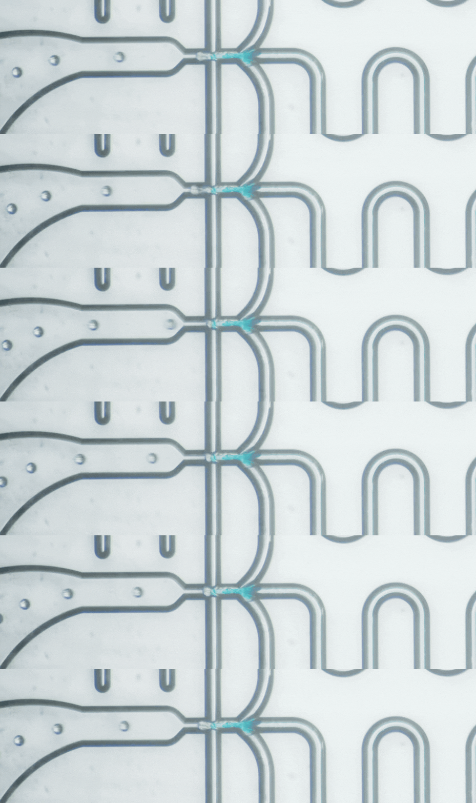
Microfluidic flow control: Syringe pumps vs pressure controllers
Microfluidic flow control affects how pressure, flow rate and fluid resistance behave across a device. This article compares syringe pumps and pneumatic pressure controllers, explains their key differences, and shows how to choose the right flow-control approach based on experimental requirements, system dynamics and integration needs.
Flow control is a fundamental part of microfluidic system design. Depending on the application, the way fluids are delivered can influence residence time, shear stress, droplet formation and other conditions inside a microfluidic device.
Microfluidic flow can be generated in several ways, including syringe pumps, pneumatic pressure control, hydrostatic pressure and integrated micropumps. This article focuses on two widely used options in benchtop microfluidic setups: syringe pumps and pneumatic pressure controllers.
Both can work well. The important difference is how they interact with the fluidic system, and therefore which experimental requirements they are best suited to.
1. How do syringe pumps and pressure controllers work?
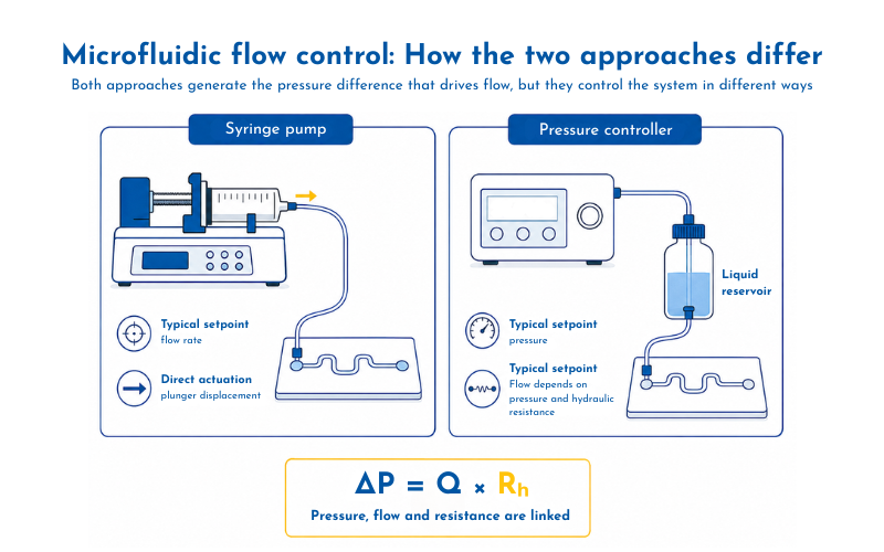
Both syringe pumps and pressure controllers ultimately generate the pressure difference required to drive fluid through a microfluidic network, but they do so in fundamentally different ways. What differs is how that pressure difference arises and which variable the device directly controls.
A syringe pump uses a motorised mechanism to move the plunger of a syringe at a defined rate. This displaces a known volume of liquid over time, so the user typically works with a nominal volumetric flow-rate setting, such as 10 µL/min.
A pneumatic pressure controller works differently. It regulates the gas pressure applied to a liquid reservoir, and that pressure drives the liquid through the connected microfluidic network.
For a fixed microfluidic network carrying a Newtonian fluid under steady laminar conditions, pressure drop and volumetric flow rate can be related through hydraulic resistance:
ΔP = Q × Rh
where ΔP is the pressure drop, Q is the volumetric flow rate and Rh is the hydraulic resistance. Hydraulic resistance depends on factors including channel geometry and fluid viscosity. [1]
This relationship explains a key practical difference between the two approaches.
With a syringe pump, the system attempts to maintain the programmed liquid displacement while the pressure required to achieve it changes.
With a pressure controller, the applied pressure is maintained while the resulting flow depends on the hydraulic resistance of the fluidic network.
Neither behaviour is inherently better. The relevant question is which variable the experiment requires you to control.
2. Syringe pumps vs pressure controllers: key differences
Syringe pumps are widely used because they are relatively straightforward to set up and allow researchers to specify a nominal volumetric flow rate directly. For many steady-flow experiments, this can be entirely sufficient.
Pressure controllers provide direct control of applied pressure and can be useful where rapid adjustments, multiple controlled pressure inputs or integration into a larger instrument are important.
The main differences can be summarised as follows:
One consideration with syringe pumps is that a conventional system controls plunger movement rather than continuously measuring the actual flow inside the microfluidic device. In sufficiently sensitive applications, mechanical behaviour can therefore become relevant. Li et al. showed that stepper-motor motion in syringe pumps could generate measurable flow fluctuations, with the magnitude depending on factors including pump design, syringe diameter and flow rate. In the droplet-generation system studied, these fluctuations could influence droplet formation. [2]
This does not mean syringe pumps are inherently unstable. In many experiments, these effects have no meaningful impact on the result.
Pressure controllers avoid the same syringe-plunger mechanism, but they introduce another consideration: constant pressure does not necessarily mean constant flow.
If hydraulic resistance changes while the applied pressure remains fixed, the resulting flow also changes. Where actual flow needs to remain controlled despite these changes, a flow sensor can be added to enable closed-loop adjustment of the applied pressure.
3. Which approach should you choose?
The choice should start with the scientific requirement rather than the controller specification.
For a simple experiment operating at a relatively steady flow rate, a syringe pump may be the most practical solution. The setup is familiar, the flow-rate setting is intuitive and additional pressure-control hardware may offer little benefit.
Pressure control can become more attractive when the experiment requires frequent or rapid changes in operating conditions. Instead of relying on mechanical displacement of a syringe plunger, the controller can adjust the pressure applied to the reservoir directly.
However, the response seen at the microfluidic device still depends on the rest of the system. Tubing, reservoirs, trapped gas and hydraulic resistance all contribute to the dynamics of the fluidic circuit.
The expected stability of hydraulic resistance is another important consideration. If viscosity changes, a channel begins to block or the fluidic pathway changes during an experiment, a fixed pressure will no longer produce the same flow rate.
Finally, consider how sensitive the scientific process is to variation.
Droplet generation, for example, can be sensitive to changes in the relative flow conditions of the different phases. In organ-on-chip systems, flow can influence shear stress, transport and the cellular microenvironment. A recent review of organ-on-chip flow-control strategies therefore emphasised that the appropriate method depends on the biological objective and required flow behaviour rather than on a single preferred pumping technology. [3]
A useful decision can usually be reached by asking four questions:
- What variable needs to be controlled: flow rate, pressure, shear stress or the relationship between multiple fluid streams?
- How quickly do operating conditions need to change?
- Is the hydraulic resistance expected to remain stable?
- How sensitive is the scientific output to variation in flow?
The level of control should match the needs of the experiment rather than simply the highest specification available.
4. Flow control is part of the wider microfluidic system
A pump or pressure controller is only one part of the fluidic system.
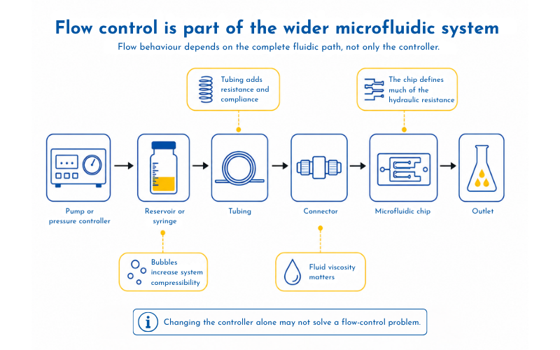
Tubing contributes resistance and compliance. Reservoir volume and headspace can affect system dynamics. Bubbles introduce compressibility. Fluid viscosity influences the relationship between pressure and flow. The microfluidic device itself defines much of the hydraulic resistance.
This means that changing the controller alone does not necessarily solve a flow-control problem.
The complete fluidic path needs to be understood.
These considerations informed the development of Blacksheep Sciences' embedded pressure-control platform for microfluidics.
The project began with a specific system requirement: pressure control needed to become part of an integrated scientific instrument rather than remain a separate benchtop component.
The resulting platform uses a distributed master–node architecture, with individual Nodes providing local closed-loop pressure regulation. During development, the system was characterised through stability, response-time and multi-channel synchronisation testing. [4]
Pressure control was not selected because it is universally preferable to syringe pumping. It was selected because its behaviour matched the requirements of that particular system.
The same principle applies more broadly to microfluidic flow control.
Syringe pumps offer a straightforward way to establish nominal volumetric flow and remain well suited to many experiments. Pressure controllers provide direct control over applied pressure and can be useful where dynamic operation, multiple controlled inputs or instrument integration are important.
The right choice starts with the experiment: understand what needs to be controlled, how the fluidic network behaves and how much variation the process can tolerate. Then select the simplest flow-control architecture that reliably creates those conditions.
At Blacksheep Sciences, our scientists and engineers develop microfluidic processes alongside the hardware and control systems used to run them. If you're exploring flow control for a new microfluidic workflow or instrument, talk to our team.
References:
[1] Oh, K. W., Lee, K., Ahn, B. & Furlani, E. P. “Design of pressure-driven microfluidic networks using electric circuit analogy.” Lab on a Chip, 12, 515–545 (2012). DOI: 10.1039/C2LC20799K.
[2] Li, Z., Mak, S. Y., Sauret, A. & Shum, H. C. “Syringe-pump-induced fluctuation in all-aqueous microfluidic system implications for flow rate accuracy.” Lab on a Chip, 14, 744–749 (2014). DOI: 10.1039/C3LC51176F.
[3] Ancelmo, H. C. et al. “Microfluidic flow control strategies for organ-on-a-chip devices: a critical review.” Discover Electronics, 3, 52 (2026). DOI: 10.1007/s44291-026-00202-1.
[4] Blacksheep Sciences. “Case study: Engineering a scalable, embedded pressure-control platform for microfluidics.” Accessed 8 September 2026.

.png)