.gif)
Beyond the junction: Wider design considerations for microfluidic chip engineering
Microfluidic chip performance depends on more than junction geometry. Explore how flow resistance, chip interfacing, materials, and manufacturing strategy influence stability, scalability, and real-world usability.
When people talk about microfluidic chip design, the conversation usually starts — and ends — with junction geometry: T-junctions, flow-focusing, step emulsification. These structures are critical for droplet formation, but they’re only one piece of the puzzle.
In real-world applications, chip performance depends just as much on system-level design decisions that determine stability, scalability, and day-to-day usability. If you’re building chips for reliable operation or scale-up, three critical factors must be properly considered: resistance, interfacing, and manufacturing.
1. Flow resistance: The hidden performance driver
Fluidic resistance is one of the most important — and most overlooked — design parameters in microfluidics. It governs how pressure is distributed across a network and ultimately determines whether a system can operate stably and scale reliably.
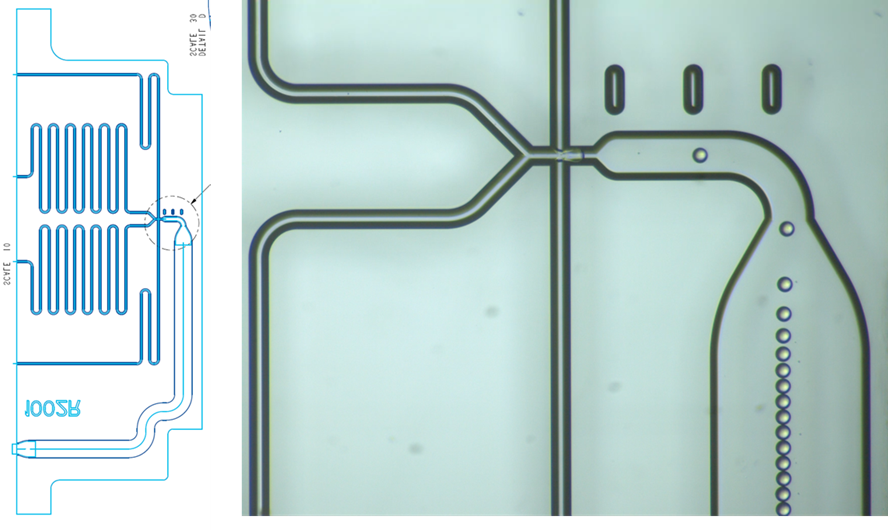
A clear demonstration of this principle can be found in the work of Adam Issadore and colleagues (Nature Communications, 2018), where large-scale droplet generation was achieved using carefully engineered flow resistance networks. In their platform, liquids were distributed across N parallel flow-focusing generators (where N = 10,260) using a shared set of distribution channels. The key design insight was to ensure that the resistance of the distribution network (RD) remained negligible compared to the resistance of each droplet generator (RDev).
This leads to a simple but powerful scaling rule:
\( 2N\left(\frac{R_D}{R_{Dev}}\right) < 0.01 \)
When this condition is satisfied, pressure variations along the network become insignificant, allowing each junction to experience nearly identical flow conditions. The result is highly uniform droplet production across more than 10,000 parallel generators— a critical requirement for industrial-scale microfluidics.
Why does resistance matter so much?
Flow resistance acts as a hidden control layer in microfluidic systems:
- Upstream resistance stabilizes flow by buffering pressure fluctuations
- Downstream resistance defines backpressure, influencing droplet pinch-off and formation dynamics
- Local (device) resistance determines how flow is distributed across different regions of a microfluidic system and how sensitive each region is to upstream or downstream disturbances.
- Reagent-dependent resistance becomes critical when viscosity changes during processes like polymer precipitation
Without deliberate resistance engineering, even small disturbances — such as pump pulsations or viscosity changes during reactions (e.g., polymer precipitation or gelation) — can propagate through the system and destabilize droplet formation.
Practical guidance for chip design
In pressure-driven microfluidic systems, most of the pressure drop should ideally occur in the channels feeding the junction, where fluid viscosity is predictable. In some cases, this means adding defined flow resistance to the feed channels to stabilise flow and keep the pump operating within a suitable pressure range.
By contrast, resistance after the junction should generally be minimised where possible, for example by reducing downstream channel length or increasing channel width and depth. This helps keep the pressure at the junction closer to atmospheric pressure, reducing the impact of downstream viscosity changes such as polymer precipitation or gelation on droplet formation.
It is also good practice to design feed channels with similar pressure drops and to operate pumps within comparable pressure ranges. Large differences in driving pressure can increase the risk of backflow between inlet channels. Incorporating sufficient resistance to require moderate driving pressure is beneficial in making the system less sensitive to minor fluctuations in pressure; however, there is a trade-off: driving pressure should not be unnecessarily high, as this may increase the risk of air absorption into fluids held in feed reservoirs.
Design insight from scalable droplet networks
The Issadore architecture shows that scalability is not achieved by simply replicating droplet generators, but by carefully balancing hydraulic resistance across the entire network. In essence, each droplet generator must be hydraulically isolated enough that global pressure fluctuations do not bias local flow rates.
This transforms microfluidic design from a purely geometric problem into a network optimization problem, where resistance ratios define performance limits.
Practical design implication
In practice, these resistance principles should be checked early in the design stage rather than after fabrication. Tools such as a pressure drop calculator and microfluidic resistance calculator can be used to estimate how pressure is distributed across feed channels, junctions and downstream sections of the device. By inputting channel dimensions, fluid properties, and flow rates, users can identify whether most of the pressure drop occurs in the intended regions, whether feed channels are reasonably balanced, and whether the required driving pressure remains within a safe operating range. This helps reduce the risk of unstable droplet formation, backflow, excessive pressure build-up, chip delamination or device failure.
This reinforces a key principle:
Even if you don’t design resistance explicitly, it will nonetheless control your microfluidic system.
2. The interface to the outside world
A microfluidic chip doesn’t operate in isolation — its real usability depends on how well it connects to the surrounding system.
Key considerations include:
- Tubing and connector compatibility
- Dead volume minimization
- Pressure tolerance under real pump conditions
- Integration with pumps, sensors, and automation
- Ease of setup for non-expert users
In practice, poor interfacing often limits adoption more than the chip design itself.
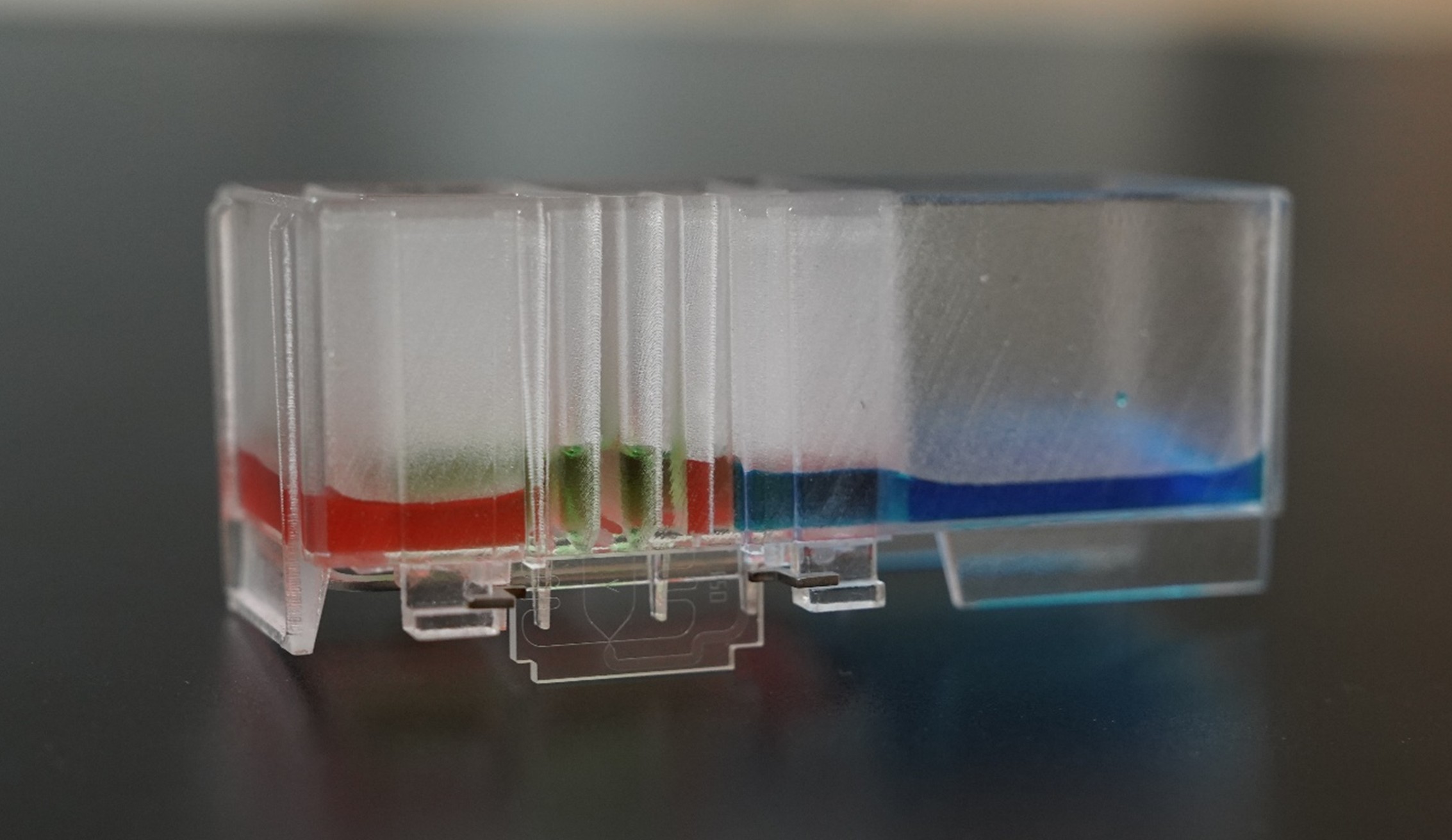
Example: At Blacksheep Sciences, we’ve explored how rethinking the chip interface can significantly improve usability. In our modular, tubeless microfluidic system, chip mounting, sealing, and fluid delivery are integrated into a single cartridge-based platform. By eliminating traditional tubing and priming steps, setup time is reduced from nearly an hour to just minutes, while also improving flow consistency by removing tubing-induced variability.
This highlights a broader principle:
Many real-world limitations in microfluidics come not from the chip itself, but from how it connects to the external system.
3. Materials & Manufacturing strategy
Material and fabrication choices ultimately determine whether a microfluidic chip remains a prototype or becomes a scalable, production-ready system.
Material selection directly impacts:
- Chemical compatibility (e.g., solvent resistance, adsorption)
- Surface properties (wettability, stability over time)
- Optical performance (for imaging and detection)
- Mechanical robustness (pressure tolerance, durability)
Example: As discussed in this article on choosing materials for microfluidic chips from Blacksheep Sciences, materials such as glass, PDMS, and thermoplastics each offer distinct trade-offs in solvent compatibility, scalability, and manufacturability. For instance, glass provides excellent chemical resistance and optical clarity, while thermoplastics enable scalable, cost-effective production, and PDMS supports rapid prototyping but is limited in solvent compatibility.
At the same time, the manufacturing method defines how a device can scale. Different fabrication approaches — including soft lithography, injection molding, etching, hot embossing, and 3D printing — each serve different stages of development, from early experimentation to high-volume production.
This highlights a key principle:
Material and manufacturing choices are not just technical decisions — they define the pathway from concept to commercialization.
4. System thinking wins
High-performance microfluidic chips are not just about geometry — they are engineered systems.
Junction design controls droplet formation, but:
- Resistance design ensures stability and scalability
- Interfaces determine usability
- Manufacturing enables real-world deployment
Teams that design with this system-level mindset build devices that run longer, scale faster, and perform reliably outside the lab.
For more practical insights on microfluidic design and scale-up, explore resources from Blacksheep Sciences.


